Tuesday, January 29, 2019

Troubleshooting Distributed Firewall in NSX-V - How to check firewall rules for a VM

Troubleshooting Distributed Firewall in NSX-V

Blog reference:

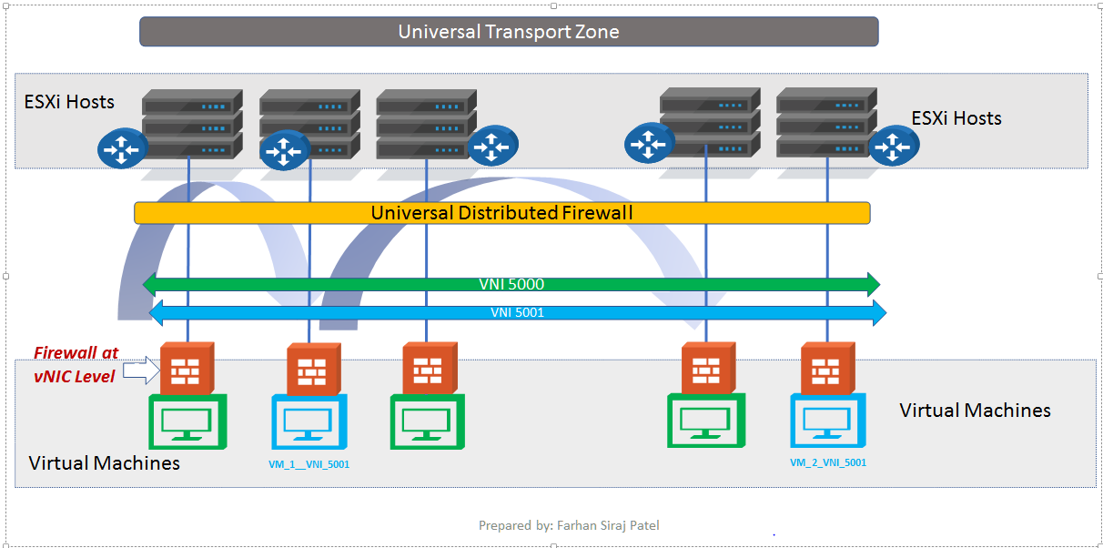
https://docs.vmware.com/en/VMware-NSX-Data-Center-for-vSphere/6.4/com.vmware.nsx.troubleshooting.doc/GUID-20234847-3E7A-4FE8-AEE1-31FFB3652481.html

 In my earlier post on Microsegmentation, we referenced the below topology and we put the workloads for different tiers - Web, App and DB on the same NSX Logical Switch.
With NSX micro segmentation, firewall is applied at vnic level of each virtual machine.

Topology

Below firewall rules are configured on DFW
Notice from the output above that firewall rules are only being applied wherever required using Applied To field


One of the troubleshooting techniques when you are checking DFW issues is to look for the firewall rules being applied at vnic level of a specific VM.


There are two ways of checking the rules
1. From the CLI of host where VM resides.
2. From NSX Manager CLI

1. From the host CLI


Login to the host where the VM resides. In our case, the VM is on host esx-03a

We will first get the dvfilter name using below command.
Notice that we are looking for output relevant to the VM name - hr-web


With this, we have got the dvfilter name.
Much easier than checking from NSX Manager CLI as you will notice.
The dvfilter name is nic-70100-eth0-vmware-sfw.2

Now we can check the firewall rules corresponding to this dvfilter using command below.


Look carefully and you will observe that only firewall rules relevant to hr-web-01a have been applied to the vnic of this VM.
From the below pic, only rule number 1, rule number 2 and the default rule is applied to this VM.
Rule number 3 is not applied because that is related to app and db virtual machines.
Hence rule number 3 will be applied to the vnic of App and DB virtual machines.
Also notice that logging is enabled for these three rules.


Filter and check the default deny rule

Addr Sets used in DFW rules

We are keen on checking the address sets and this can be done using the command above.


2.  Let's also check the firewall rules applied to vnic of VM from NSX Manager CLI

For this, we will begin by checking the host where our VM resides. 


Notice from the output above that the VM resides on host esx-03a 

Let's also check the cluster corresponding to this VM

 Next up, we need the cluster ID to know the host ID 

We now need to find dvfilter for the VM using the host ID, host ID in our case is host-32


Now that we know the dvfilter, we can go ahead and check the rules applied to the vnic of VM


Notice from the output above that you are able to view the TCP rules applied to the vnic of VM hr-web-01a
Corresponding address sets are also listed.

==================================================================

Troubleshooting DFW using Vrealize Log Insight


For the integration of Vrealize Log Insight server along with NSX:

1. We need to forward logs from the hosts to Vrealize Log Insight VRLI server
2. Forward logs of NSX edges and DLR to Vrealize Log Insight Server
3. Forward logs of NSX Manager to VRLI server.
4. Forward logs of NSX controllers to VRLI server.

We will be sending ICMP traffic towards the web server. DFW is blocking this traffic.
We should see this event on the web console of VRLI server.

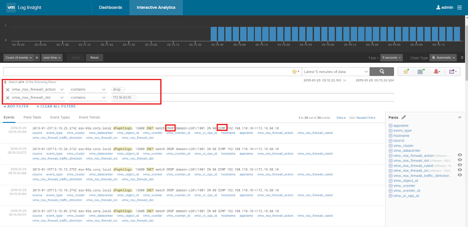
ICMP traffic is blocked by DFW as per configuration

HTTPS traffic towards the web server is allowed


Wednesday, January 16, 2019

VMware NSX Microsegmentation - Securing Collapsed Architectures

VMware NSX Microsegmentation - Securing Collapsed Architectures


As depicted in above topology, NSX-V Distributed Firewall feature is enabled.
And as shown in figure above, firewall is effectively applied at each vNic of virtual machine.

In this topology:


  1. BGP is used as routing protocol
  2. iBGP is used within NSX
  3. eBGP is used between NSX edges and the physical ToR switches
  4. Physical switches are Juniper QFX Virtual Chassis.
  5. ToRs are advertising a default route towards NSX edges only. NSX domain uses this default route for egress traffic from the NSX domain.

A different logical switch is used for each of the three tiers viz. Web, App and Database.

In this post, we are going to showcase a key ability of NSX whereby it can impose a zero trust model and secure VMs from different tiers on the same logical switch. We are not creating a logical switch per tier in such a topology.
This new topology is as shown below.


Notice, there is a single logical switch to which Web, App and DB VMs are connected.

We will leverage Vrealize Network Insight to plan security here.


VMware vcenter server and VMware NSX manager both are added as data sources in Vrealize Network Insight.


Using the information presented to us by Vrealize Network Insight, we will populate rules on our NSX Distributed Firewall.

The IP addresses of the VMs connected to the logical switch are:
Web - 172.16.60.10
App - 172.16.60.11
DB - 172.16.60.12

Using flow queries on Vrealize Network Insight, we are able to fetch information related to destination ports.


Next, we are going to create security groups using dynamic membership criteria.
This is to showcase the ability of NSX to create dynamic security groups based on VM names.


In future, if they add more virtual machines with VM name as hr-web-02, then such a virtual machine will automatically be a part of the security group based on dynamic membership criteria as defined above.

We then define the rules on NSX Distributed Firewall.


Here, we are making sure that only required communication is allowed on the distributed firewall and everything else is blocked.
This can be seen by the default rule in pic above which is set to Block

We then verify that our rules are working as intended:


Ping from Web to App fails


We are able to connect to the web server and even though the three virtual machines belong to the same logical switch / subnet, the web server is unable to ping other machines on the same logical switch.
Effectively this is a zero trust model.


Further verification commands have been executed on Web and App VMs to illustrate that firewall rules are effective allowing only what is required and denying everything else.


Tuesday, July 25, 2017

VMWare NSX Distributed Firewall


We tried to cover VXLAN and VXLAN traffic flow earlier.

Every solution has three main components to it - Management, Control and Data Plane.

NSX Manager is the management component of VMware NSX solution

We now try to know more about Data Plane components of NSX.

Data Plane of NSX has:
·         Logical Switch
·         Logical Router
·         NSX Edge ( NSX Edge has firewall, DHCP relay, load balancer, NAT and IPSec features
·         Distributed firewall


We will be discussing the NSX distributed firewall in this blog post.


In the figure above, there is

a.    Transport Zone
Which spans multiple clusters in different sites.
You are able to provision multiple logical switches within a transport zone.

What is a cluster?

Cluster is collection of hypervisors


b.    Two logical switches with Virtual Network Identifiers VNIs 5000 and 5001

VNI is used to identify the overlay created over physical network.

c.    We know that virtual machines in NSX infrastructure connect to Logical Switches.
There are two virtual machines connected to logical switch with VNI 5001

d. Distributed firewall of NSX is applied to each vNIC of all virtual machines.


Features of Distributed Firewall:


1.    Takes care mainly of East - West Traffic within your Data Center.

For illustration purpose, figure below illustrates East West traffic within Data Center.

·         Data Center Firewall has two logical DMZs
·         One for Application Server Farm and the other for Database Server Farm.

Flow of traffic from Application Server towards Database Server is East West in terms of direction.


There is a separate data plane component - NSX Edge Services Gateway which handles north south traffic in a Data Center.

2.     Firewall is applied at vNIC level of each virtual machine.
Traffic optimization is achieved here and you don't have unnecessary traffic being thrown into the external physical network.
If the firewall policy applied at vNIC level doesn't permit the traffic, the traffic is blocked closest to the source virtual machine.

Ideally with traditional Data Center networks, such traffic would traverse northbound towards physical Data Center firewall and would be dropped by the firewall if the action on firewall is to Deny the traffic.

3.    Distributed firewall rules can be written using L2 rules or L3/L4 rules.
We need to keep in mind that L2 rules are enforced before L3/L4 firewall rules.

4.    The throughput of Distributed Firewall improves as more hypervisors/VTEPs are added to the NSX infra.

Rules in Distributed Firewall can be based on:
                         i.         Port group
                        ii.         Logical switch
                       iii.         Distributed port group
                       iv.         Virtual machine name
                        v.         Operating system name
                       vi.         Data center
                     vii.         Cluster


For example you can create a rule on NSX Distributed Firewall in this way:

Source -
App Logical Switch

Destination -
Database Logical Switch

Destination Port - tcp/1433

This will allow all virtual machines connected to App Logical Switch to talk to all virtual machines connected to Database Logical switch over tcp port 1433

5.    Throughput of Distributed Firewall increases as more and more hypervisors are included.

6.    There is also integration with other vendor firewalls like Palo Alto.
In addition to  content filtering techniques of Palo Alto firewall, you are able to integrate other security features of Palo Alto Next Generation Firewall like vulnerability protection, antivirus, anti-spyware.


Wednesday, June 8, 2016

QoS on Palo Alto Firewall

Quality of Service on Palo Alto Firewall


Reference:


 1. The process of classification
Anyone who has prior experience of Modular QoS CLI (MQC) on Cisco IOS will know that you first classify traffic that needs to be prioritized against other types of traffic.

Similar logic is applied while configuring QoS on Palo Alto firewall.

The first step towards configuring QoS on Palo Alto firewall is to classify the traffic.

Palo Alto allows you to classify traffic based on several parameters like:

  1.  Source zone
  2.  Source IP/subnet
  3.  Source user
  4.  Destination zone
  5.  Destination IP/subnet
  6.  Application
  7.  TCP/UDP service
  8.  URL category


You identify the traffic that needs preferential treatment and assign it to a class.
On Palo Alto firewall, you have 8 classes of traffic; so your traffic will eventually fall in one of the eight classes.
Also in this step, you are able to leverage App ID and User ID features of Palo Alto to classify traffic.


 2. Create a QoS Profile

Let us say that you have classified youtube traffic into class1
When you create a QoS profile for youtube traffic, you can set:

a. Priority
There are four configurable priorities – real time, high, medium and low
Real time being most important.

 b.  Egress Max
Maximum bandwidth to be set for this class.
Traffic beyond this rate will be dropped. This is similar to policer mechanism in Cisco IOS.

c. Egress Guaranteed
Amount of bandwidth which is guaranteed at all times.

In below example, you are setting 6 Mbps maximum bandwidth for youtube traffic and also giving youtube traffic guaranteed bandwidth of 3 Mbps


 3. Apply the QoS profile on physical interface.

Here you simply apply the QoS profile created in Step 2 above to a physical interface.


 4. Verification

To ensure that your configuration is indeed working, you need to navigate to
Network – QoS – Statistics
Where you will be able to verify your configuration.

Tuesday, April 5, 2016

DNS Sinkhole feature on Palo Alto Firewall

DNS Sinkhole feature on Palo Alto Firewalls


References:

https://www.paloaltonetworks.com/content/dam/pan/en_US/assets/pdf/framemaker/60/pan-os/NewFeaturesGuide/section_3.pdf

https://www.sans.org/reading-room/whitepapers/dns/dns-sinkhole-33523


Why use DNS Sinkhole?

Picture this that you have infected hosts on your network that are connecting to malicious websites, websites and portals that are totally not secure. DNS resolution and DNS queries play a vital role here in such communication.

When there is a DNS query for malicious domain, Palo Alto firewall can identify this and cause malicious domain to be resolved to a SINK HOLE IP ADDRESS that you provide/configure.

Palo Alto supports both IPv4 and IPv6 DNS Sinkhole address.

Configuring DNS Sinkhole on Palo Alto Firewall:

DNS Sinkhole configuration on Palo Alto firewall is as simple as including DNS sinkhole IPv4 address in antisypware security profile on Palo Alto.

This security profile will then be called in a security policy on the firewall allowing outbound DNS communication.

Important note here is that sinkhole address should belong to a zone on firewall other than the zone where DNS query is received.

https://live.paloaltonetworks.com/t5/Configuration-Articles/How-to-Configure-DNS-Sinkhole/ta-p/58891

Sunday, March 20, 2016

Content Filtering Techniques on Palo Alto Firewall

Content filtering techniques on Palo Alto firewall


1. URL filtering

URL filtering allows you to block web browsing based on URL category.

For example, you could block these categories available on Palo Alto - abused drugs, alcohol and tobacco, phishing, peer to peer.

Palo Alto also allows you to check URL category for a particular website.
'Check URL category' feature on Palo Alto firewall will redirect the user to a website where URL category can easily be determined.

You can also create a custom URL category and specify websites here in the URL category.
The URL category can then be controlled using actions like alert, allow, block, continue, override.

More on the actions is here

Response pages is something where the user would see a particular HTML page.
And this page would notify the user that URL is not allowed as per the internal company policy.


2. Application based filtering
Palo Alto firewalls have the App ID feature.
This essentially allows users to block applications like dropbox, skype very easliy.

So when you configure the security policy on Palo Alto, you specify the application type in addition to other parameters like

a. Source zone
b. Source user
c. Source IP
d. Destination zone
e. Destination IP
f. Application - YOU SPECIFY THE APP HERE
g. LEAVE SERVICE TO APPLICATION DEFAULT
h. URL category
i. Action
j. Security Profiles


3. File blocking
Here you could block upload/download of specific file types like .exe, .pdf, .rar
And these file types could be blocked for specific applications like gmail.
Several actions are available namely:
a. Alert
b. Block
c. Continue
d. Forward
e. Continue and Forward

You may find more on these different actions here


Thursday, March 17, 2016

Palo Alto - x forwarded for feature

Enterprise internet set ups incorporate systems like Proxy Servers.
Such systems help cache internet data and eventually save a lot of internet bandwidth and cost.

What do proxy servers additionally do?

a. Source NAT (SNAT) client IPs and source internet traffic from itself.
Here you are hiding/masking client IP address. Such mechanism prevents client IP addresses from being spoofed.
To sum this up, when IP packet passes through a proxy server, source IP field of the IP packet is modified and source is changed to be IP address of proxy server.

b. Along with this, the proxy server will add “x-forwarded-for” in the http GET request from the client and client IP address to this field.
So the original client IP information is retained in the IP packet using x-forwarded-for field.

Picture this now, your internet destined traffic coming out of the proxy server now flows through Palo Alto firewall deployed in transparent mode.

And the traffic flow is something like this

Client system - Proxy Server - Palo Alto firewall (transparent mode) - Internet Router - Internet Cloud.

And the return traffic will be
Internet Cloud - Internet router - Palo Alto firewall (transparent mode) - Proxy server - Client system

Now with a proper Security Incident & Event Management (SIEM) solution in place, traffic flowing through Palo Alto firewalls could now be logged.
And the x-forwarded-for option will reveal the actual client IP on the logging system.

The x forwarded for feature on Palo Alto is covererd here:


https://live.paloaltonetworks.com/t5/Learning-Articles/X-FORWARDED-FOR-Feature-in-PAN-OS-6-1/ta-p/53879